


Concentric Reducing Metal Hose Pump Connector – 150# Flanged
From $198.60
Hose: 321 stainless steel corrugated, braided with 304 stainless steel. Flanges: carbon steel, Class 150 drilling compatible with ASME B16.5 bolt circles. Welded construction throughout the pressure boundary. Select size and overall length below.
Description
A reducing pump connector solves a specific installation problem: the pump nozzle and the connected piping are different nominal sizes. Instead of stacking a reducer, a flexible connector, and extra flange pairs – adding cost, weight, leak paths, and face-to-face length – this assembly builds the concentric reduction directly into a braided 321 stainless steel hose assembly with 150# flanges on both ends. The result is a single component that isolates pump vibration, accommodates minor misalignment, and transitions between line sizes in one bolt-up. Three reductions are stocked: 3″ x 2″, 4″ x 2″, and 4″ x 3″, in overall lengths from 13 to 24 inches. These cover the most common base-mounted and inline centrifugal pump combinations found in hydronic and condenser water systems. Other reductions, eccentric configurations, and 300# flanges are available as engineered fabrications.
Key Features
- Concentric size reduction integrated into the hose assembly – no separate reducer fitting
- 321 stainless steel corrugated hose with 304 stainless braid
- Carbon steel 150# flanges, drilling per ASME B16.5 bolt pattern
- Three stocked reductions: 3″x2″, 4″x2″, 4″x3″
- Overall lengths 13″–24″ to match typical pump layout dimensions
- Reduces flanged joints and potential leak paths versus reducer-plus-connector stacks
Applications
Centrifugal pump suction and discharge connections where pump nozzle size differs from line size; chilled water, condenser water, and heating water systems; cooling towers; booster pump skids. Purchasers are typically mechanical contractors and pump skid OEMs. Typical media: water, glycol, and other media compatible with 300-series stainless hose and carbon steel flanges.
Materials & Construction
Hose: 321 stainless steel corrugated, braided with 304 stainless steel. Flanges: carbon steel, Class 150 drilling compatible with ASME B16.5 bolt circles. Welded construction throughout the pressure boundary.
Pressure, Temperature & Application Review
Allowable pressure and temperature depend on both connection sizes, hose construction, braid, flange design, operating temperature, media, movement, bend radius, cycle requirements, and installation geometry. Do not select this reducing connector from nominal size or flange class alone. Submit the design conditions when the service is critical or outside normal mechanical-piping conditions.
Displayed prices and selectable configurations do not constitute a certified pressure rating, code-compliance determination, or engineered system approval.
Testing & Documentation
Testing, tagging, material documentation, and written reports are available only when included in the accepted quotation or order acknowledgment. State all testing and documentation requirements before production release.
Ordering Notes
Select the reduction (larger end x smaller end) and overall flange-face-to-flange-face length. Confirm bolt-up orientation during installation – the reducing end should mount at the pump nozzle unless the design states otherwise. Eccentric reductions and stainless flanges are quoted on request. All assemblies are made to order; published ratings apply at
70°F and derate with temperature. Applications outside published ratings require
engineering review before order – request a custom quote and our engineering team will
respond with a certified configuration.
Related Products & Resources
- flanged metal hose assemblies
- Quick Ship metal hose
- expansion joints
- Engineering Hub
- request a custom quote
- 321SS Braided Metal Hose Assembly – 304SS Sch.40 Male NPT x Male NPT
- 321SS Double-Braided Metal Hose – Carbon Steel 300# RFSOF Flanges
- 321SS Braided Metal Hose – Carbon Steel 150# Raised-Face Flanges
Browse all metal hose assemblies, unbraided metal hose, and
expansion joints, or visit the Engineering Hub for selection guides,
calculators, and specification resources.
Order Now
Select your configuration above and add to cart – availability and release timing are confirmed during order review. Need a variant you don’t see, certified test reports, or an
engineered submittal? request a custom quote, call 763-200-2287,
or email [email protected].
Technical Documents
- Metal Hose Pressure & Temperature Ratings (TD-100)
- Metal Hose Assembly Catalog (CAT-200)
- Hydrostatic Test Report Template (QF-400)
Engineering Calculators & Selection Tools
- Metal Hose Pressure Derating Calculator
- Metal Hose Length & Bend Radius Calculator
- Thermal Expansion & Offset Calculator
- Velocity & Pressure Drop Calculator
- All Engineering Calculators
Use calculator outputs as preliminary selection inputs. Final assembly suitability depends on product-specific pressure, temperature, movement, fittings, media, cycling, and installation conditions.
PDF Submittal Attachments
This PDF is provided as a sample/reference block for pump-connector submittal coordination. Final documentation for a configured order is reviewed against the selected inlet/outlet sizes, overall length, flange details, pressure, temperature, media, movement, and project requirements.
Additional information
| Weight | N/A |
|---|---|
| Hose ID | 3 x 2 in., 4 x 2 in., 4 x 3 in. |
| Overall Length | 13 in., 14 in., 15 in., 16 in., 16.5 in., 17 in., 17.5 in., 18 in., 18.5 in., 19 in., 19.5 in., 20 in., 24 in. |
Related products
-
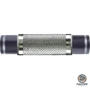
321SS Braided Metal Hose – Sch.40 Victaulic-Compatible Grooved Ends
From $181.99Select options This product has multiple variants. The options may be chosen on the product page -
321SS Braided Metal Hose – 150# Female NPT Union Ends
From $24.99Select options This product has multiple variants. The options may be chosen on the product page -
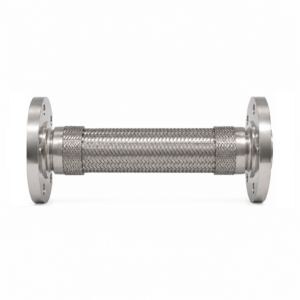
316SS Double-Braided Metal Hose Assembly — 150# Flange x 150# Flange
Select hose ID and enter OAL for configured pricing.Select options This product has multiple variants. The options may be chosen on the product page -
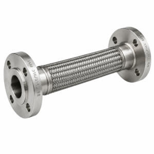
316SS Double-Braided Metal Hose Assembly — 300# Flange x 300# Flange
Select hose ID and enter OAL for configured pricing.Select options This product has multiple variants. The options may be chosen on the product page