

321SS Braided Metal Hose – Sch.40 Victaulic-Compatible Grooved Ends
From $181.99
Hose: 321 stainless steel, annular corrugated. Braid: 304 stainless steel, single layer. Ends: carbon steel Schedule 40 nipples, grooved per ANSI/AWWA C606 standard groove dimensions. Welded construction. Select size and overall length below.
Description
Grooved mechanical piping dominates modern fire protection, HVAC, and industrial water systems because it installs fast and comes apart just as fast. This assembly extends those advantages to the flexible connector: 321 stainless steel corrugated hose with 304 stainless braid, terminated in Schedule 40 carbon steel grooved nipples cut to standard roll-groove dimensions compatible with Victaulic-style couplings. The grooved ends connect with compatible couplings and gaskets rather than threaded joints or flange bolt patterns; install and torque the coupling hardware in accordance with the coupling manufacturer’s requirements. Use it at pumps and air handlers in grooved hydronic systems, at grooved-connected chillers, and anywhere a grooved system needs vibration isolation or flexibility for thermal movement and minor misalignment. Seven hose sizes are selectable in overall lengths from 12 to 30 inches; availability and release timing are confirmed during order review. Groove dimensions follow ANSI/AWWA C606 standard grooving, so the assembly accepts the same couplings and gaskets as the adjacent pipe.
Key Features
- Sch.40 carbon steel grooved ends, standard groove per ANSI/AWWA C606
- Compatible with Victaulic-style rigid and flexible couplings
- 321 stainless corrugated hose, 304 stainless single braid
- Serviceable grooved connections – disconnect the assembly without cutting welded pipe when the coupling system permits
- Seven selectable sizes; overall lengths 12″–30″
- Stainless wetted path within a grooved carbon steel system
Applications
Grooved hydronic and condenser water systems, pump rooms, air handler coil connections, grooved-connected chillers and cooling towers, and industrial water distribution. Typical media: water, glycol solutions, and compressed air. Purchasers include mechanical contractors standardized on grooved installation and facility teams retrofitting vibration isolation into existing grooved systems.
Materials & Construction
Hose: 321 stainless steel, annular corrugated. Braid: 304 stainless steel, single layer. Ends: carbon steel Schedule 40 nipples, grooved per ANSI/AWWA C606 standard groove dimensions. Welded construction.
Pressure, Temperature & Application Review
Allowable pressure and temperature depend on hose size, braid construction, fitting design, operating temperature, media, movement, bend radius, cycle requirements, and installation geometry. Do not select this assembly from nominal size or connection type alone. Submit the design conditions when the service is critical or outside normal mechanical-piping conditions.
Displayed prices and selectable configurations do not constitute a certified pressure rating, code-compliance determination, or engineered system approval.
Testing & Documentation
Testing, tagging, material documentation, and written reports are available only when included in the accepted quotation or order acknowledgment. State all testing and documentation requirements before production release.
Ordering Notes
Select size and overall length, measured end of groove to end of groove. Couplings and gaskets are not included – use the same style as the adjacent piping. For grooved x flanged, grooved x weld, or stainless grooved nipples, request a custom quote. Assemblies are released only after order review. Product-specific working-pressure, temperature-derating, bend-radius, and fitting-limit data must be validated for the selected configuration before those values are used for design. Submit operating conditions through the engineering RFQ when those limits are required.
Related Products & Resources
- grooved metal hose assemblies
- Quick Ship metal hose
- metal hose assemblies
- metal hose selection guide
- Engineering Hub
- 321SS Braided Metal Hose Assembly – 304SS Sch.40 Male NPT x Male NPT
- Concentric Reducing Metal Hose Pump Connector – 150# Flanged
- 321SS Double-Braided Metal Hose – Carbon Steel 300# RFSOF Flanges
Browse all metal hose assemblies, unbraided metal hose, and
expansion joints, or visit the Engineering Hub for selection guides,
calculators, and specification resources.
Order Now
Select your configuration above and add to cart – availability and release timing are confirmed during order review. Need a variant you don’t see, certified test reports, or an
engineered submittal? request a custom quote, call 763-200-2287,
or email [email protected].
Technical Documentation
Controlled product-specific pressure/temperature ratings, certified drawings, submittals, and test documentation are supplied only when the applicable source and configuration have been validated. Request required documentation through the engineering RFQ before production release.
Engineering Calculators & Selection Tools
- Metal Hose Pressure Derating Calculator
- Metal Hose Length & Bend Radius Calculator
- Thermal Expansion & Offset Calculator
- Velocity & Pressure Drop Calculator
- All Engineering Calculators
Use calculator outputs as preliminary selection inputs. Final assembly suitability depends on product-specific pressure, temperature, movement, fittings, media, cycling, and installation conditions.
Additional information
| Weight | N/A |
|---|---|
| Hose ID | 2.00 in., 2.50 in., 3.00 in., 4.00 in., 5.00 in., 6.00 in., 8.00 in. |
| Overall Length | 12 in., 13 in., 14 in., 15 in., 16 in., 18 in., 20 in., 21 in., 22 in., 23 in., 24 in., 25 in., 26 in., 28 in., 30 in. |
Related products
-
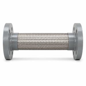
321SS Braided Metal Hose – Carbon Steel 150# Raised-Face Flanges
From $145.00Select options This product has multiple variants. The options may be chosen on the product page -
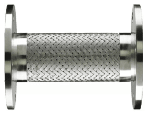
321SS Braided Metal Hose – 304SS 150# Fixed Plate Flanges
From $186.97Select options This product has multiple variants. The options may be chosen on the product page -
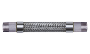
321SS Braided Metal Hose Assembly – 304SS Sch.40 Male NPT x Male NPT
From $58.04Select options This product has multiple variants. The options may be chosen on the product page -
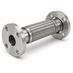
321SS Braided Metal Hose – 304SS 150# Flat-Face Floating Flanges
From $186.97Select options This product has multiple variants. The options may be chosen on the product page